![]()
![]()
TRMA Tech Feature of the Month
May 2005
Titanic's Steering Engines
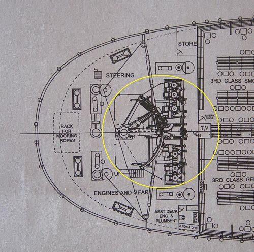
Under the poop deck, aft of the 3rd class General Room, sat Titanic's massive steering engines. To some, the idea of an engine to power the steering mechanism may seem odd - but unlike the rope-and-tiller steering arrangement in large sailing ships, where the tiller ropes connected directly to the ship's wheel, a ship Titanic's size needed much more power. Titanic's rudder weighed 101 1/4 tons, and no steering arrangement involving manual power, regardless of how much leverage was in the system, would have sufficed to move it. In addition, a rudder is moved side to side by applying a rotational power to the shaft, which presents no mechanical advantage. (To get an idea of the amount of force required, try to open and close a heavy door in your house by holding it on top at the hinge side.) Plus, there was the force of the waterflow along the hull acting against the rudder, which needed to be not only met but overcome. Thus, the need for a steering engine which could deliver the massive power required.

Detail from General Arrangement plans courtesy
Bruce Beveridge. Copyright 2004 Bruce Beveridge.
A full set of these plans is available for purchase -
click here.
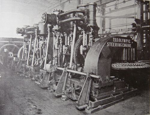
Titanic actually had two steering engines, each mounted just off to the left and right of the ship's centerline. Only one was actually used at any given time, the other being kept in reserve as a standby. Olympic's is shown below. Each was powered by the ship's steam supply under pressure from the boilers, and had cylinders much like the reciprocating engines.

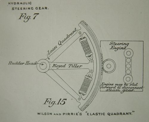
The diagram below depicts a Steering Quadrant, which is the mechanism by which
the rudder post was actually pivoted (rotated). It is called a Quadrant
because in shape it's close to one quarter of a circle. Gears
on the outside meshed with those on the steering engines, (only one is shown
in the diagram below) and depending on the direction the gears turn, the rudder
moved either to the right or to the left. The Quadrant was not directly
connected to the rudder post, for to do so would have subjected the steering
engines to shocks and stress that they could not absorb. Instead, the
outer arms of the Quadrant were connected to a hub that sat freely on the
rudder post. A separate center arm also sat on the rudder post, between
the outer arms, but was connected (keyed) solidly to the post, and linked
to the outer Quadrant arms by heavy springs. In this manner, the steering
engines could apply the rotational force required to move the rudder, but
shocks and momentary resistance from changes in direction, the rudder striking
an underwater object, or surges in waterflow could be absorbed by the springs.

In the diagram at the top of the page, two warping capstans can also be seen on each side of the steering gear. In the unlikely event that both steering engines were disabled, the rudder could also be turned by rigging the steering gear to the capstans by means of wire rope. In the diagram, they are shown rigged for this purpose.
The constant noise and vibration of the steering engine, although not excessive on the Olympic-class ships, made life in the aft 3rd Class accommodations somewhat less desirable than in 1st Class - and it's from their proximity to the steering gear that 3rd Class was dubbed "steerage".
Have a question on this item? Post it on the TRMA Titanic Forum.
Copyright © Titanic Research & Modeling Association