![]()
![]()
TRMA Tech Feature of the
Month
November 2005
Compass Platform

Titanic
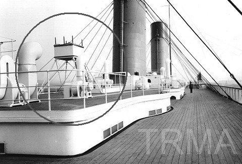
was constructed with a compass platform on the Boat deck, located amidships
between the 2nd and 3rd funnels. Although it seems odd to have a compass located
here, away from the bridge, this compass served a purpose somewhat different
than the one on the bridge and its position here was determined by certain
requirements. The compass on the platform was designed primarily for taking
bearings for navigation*. The compass on the bridge was a steering compass:
it was designed primarily to be viewed by the helmsman at the wheel. This,
along with its position inside the bridge, made it unsuitable for taking accurate
bearings. Thus, another compass was needed in a position of superior visibility,
and placing one in the center of the boat deck was ideal. Elevating it on
a platform out in the open had the benefit of raising it above visual obstructions
on deck, and also helped to minimize the magnetic influence of the iron on
the ship**. Being almost amidships, it was found that this was the area
of the ship to have the least amount of magnetic interference brought on by
the surrounding structures of the hull. The floor of the compass platform
was raised 12 feet above the deck, and the structure was constructed with
as little iron as possible to eliminate as much ferrous influence in the immediate
vicinity of the compass. A canvas cover was secured over the platform when
not in use.
The compass mounted on the platform is listed in Titanic's specifications as a
"Kelvin Standard compass with azimuth mirror." The azimuth mirror was a device
that allowed an officer to determine the exact bearing of a star, even if it was
at some altitude above the horizon. Celestial navigation was highly advanced in
1912 and even today approaches the accuracy of satellite navigation. This
compass could also be used to take terrestrial bearings (points on land) with
great accuracy. Also, since this compass was theoretically the most
accurate one on the ship (being the most free from magnetic interference from
the ship itself), it could also be used to check the accuracy of the steering
compass on the bridge.
For further information on the navigation that would have been done by Titanic's
officers, see this fine article by Dave Gittins at
http://users.senet.com.au/~gittins/navigation.html.
*It was not a "backup compass" for steering the ship; there was no telephone
link between the compass platform and the bridge, and Titanic was equipped with
another compass and a helm at the docking bridge in the event the ship could not
be steered from the navigating bridge.
**A compass points north because the magnetized needle - the one that points
"North" - is attracted by the faint magnetic pull of the magnetic North pole.
However, placing such a compass aboard an iron ship presents problems: the iron
of the ship, including the iron of the bridge all around the compass, affects
this magnetic pull. For a compass that must be placed inside the ship's
structure, there are other ways of compensating for this.

Photo courtesy
of David Cotgreave
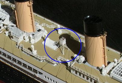
For those building a model of
Titanic, the compass platform in the 1:350 Minicraft kit can be replicated with
greater detail by using photoeteched brass parts instead of the plastic
components from the kit.
As a side note: the Kelvin compass is named for Lord Kelvin, who revolutionized the design of the marine compass. Lord Kelvin (born William Thomson) was a professor at Glasgow University in Scotland. He held patents for 70 different inventions, including the Kelvin sounding machine on Titanic. He was made a peer by Queen Victoria in 1892, at which time he chose the title Baron Kelvin.
Have a question on this item? Post it on the
TRMA Titanic Forum.
Copyright © Titanic Research & Modeling Association