![]()
![]()

Titanic's Engine Rooms
Part 2: Back to the Boilers
TRMA Tech Feature of the Month
March 2006
by Art Braunschweiger, TRMA
with technical information provided by Scott Andrews
Once
the steam had done its work in the engines, it
needed to be returned to the boilers in the form of water – properly referred to
as “feed water” - so that it could be reheated into steam again. Further, to
reduce the amount of fuel consumed in producing steam from the returned feed
water, its temperature needed to be raised prior to entering the boilers again.
Although the exhaust steam from the engines was at lower than atmospheric
pressure - only 1 PSIA - and was much cooler than when it left the boilers, it
was still a vapor and needed first to be condensed to water. This task was
accomplished by the condensers. The main purpose of these condensers was
two-fold. The first and most obvious purpose was the condensing of spent steam
from the engines back into feed water for return to the boilers; the second
purpose, and by no means the least important one, was to maximize engine
efficiency by greatly extending the lower range to which the steam could be
expanded, by creating and maintaining a vacuum into which the spent steam from
the engines exhausted. This vacuum is created by the cooling of the steam being
admitted into the condenser; as the steam condenses, both its temperature and
volume decrease, which, in turn, causes the pressure within the condenser to
decrease. By extension, a vacuum is induced within the turbine case and also in
the exhaust, or “eduction” pipes connected to the LP cylinders of the
reciprocating engines, which were all connected in line to the exhaust steam
inlets of the condensers.
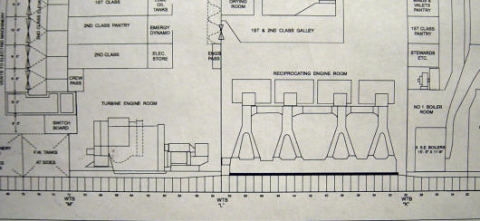
Exhausted steam exited the turbine casing through two large rectangular openings
on either side, leading to a large condenser on each side. As discussed in Part
1, the steam would also be piped directly to the condensers, bypassing the
turbine, when the reciprocating engines were running astern or at less than half
speed.
The two huge condensers, one on each side of the turbine engine, were
constructed similar in nature to an automobile radiator; however, unlike a
radiator, the tubes were entirely enclosed within the condenser housing, or
“shell”. Exhaust steam entered the condensers through the top and was directed
downwards, flowing over and around the tubes within the shell. At the same
time, cold sea water was circulated through the tubes, drawing off the last bit
of remaining heat from the steam and causing the water within the vapor to
condense and collect on the cold tube surfaces. From here, the water fell in a
heavy shower to the bottom of the condenser shell.
While only fresh water could be used to supply the boilers, seawater could readily be used to cool the tubes of the condensers. The cold water from the sea functioned admirably to cool the steam in to water, after which point it was pumped through the return feed system back to the boilers.
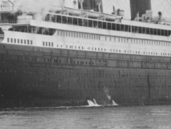
The pumps circulating the huge volumes of seawater through the condensers drew
from inlets on the underside of the hull and discharged them through twin outlets
located in a recessed trunk on each side of the ship near the water line. This
discharge of water, in two powerful streams, is readily visible in most photographs
of Titanic.

In
the photo at right, the condenser discharge is the aftmost discharge (furthest
to the left). seen here.
The ship is riding light in this photo; when fully loaded the discharge would
normally be at or near the waterline.
Information on modeling these discharges for the 1:350 Minicraft kit can be found on the Rivet Counter Scale Modeling Tutorial site at http://rivetcounter.txc.net.au/Tutorial/Alteration_Pages/27Hull.html.
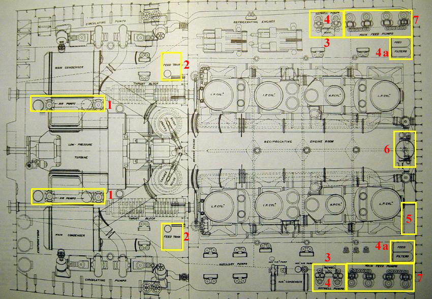
The steam entering the condensers, having been cooled (condensed) to water, was then returned to the boilers by means of the return feed system as follows. The numbers on the following diagram reference the numbers in the text that follows, as explained by Scott Andrews:

1. Weir “Dual” air pumps - two sets at each
condenser - drew off the condensed steam from the condensers. Air and
non-condensable gasses were also drawn off and discharged along with the
circulating water discharge. (This second step was essential to maintain the
vacuum within the condensers, and to prevent the feed water collecting in the
bottom of the condenser shell from becoming permeated by these gasses. The type
of air pump employed had two pump barrels – one for removing the collected feed
water at the bottom of the condenser, and one for removing the waste gasses –
hence the “dual” model designation.) The condensed steam, now termed feed
water, was discharged through a separate line.
2. From each condenser, the feed water collected in two tanks against the
forward bulkhead to the turbine engine room, one tank on each side. These were
called the feed tanks, each of which had a capacity of 2,790 gallons.
3. From each feed tank, the feed water was piped through the watertight bulkhead
to drain, by gravity, into another tank on each side of the reciprocating engine
room. These were called the hotwell tanks, each of which measured 4' x 4' x 3'.
4. Twin pumps on each side, called hotwell pumps, drew the feed water from the
hotwell tanks and forced it through feed filters (4a on diagram), one pair on
each side, located on the forward bulkhead of the engine room. These did just
what their name implied, removing grease, lubricating oil and other hard
contaminants from the feed water.
5. The filtered feed water, under pressure, was piped upward to a surface feed
heater. Inside this heat exchanger, the feed water flowed through tubes, while
exhaust steam from the main generator sets passed through the shell and around
the tubes. This made efficient use of the heat contained within this exhaust
steam, and raised the temperature of the feed water to 140 degrees F. (At this
point, the steam from the generator sets, having condensed on its way through
the surface heater, was drained off to the feed water tanks where it was added
back into the feed water supply.)
6. From the surface feed heater, the feed water (still under pressure) was piped
upward to a single direct contact heater located high on the forward engine room
bulkhead. This functioned to raise the temperature of the feed water even
higher. Inside the direct contact heater the feed water, passing through a
spring-loaded valve, dropped through a conical dispersion plate, which caused it
to fall in droplets through a cloud of exhaust steam being admitted from the
ship's many auxiliary engines, simultaneously raising the temperature of the
feed water to 230 degrees F and condensing the incoming exhaust steam, while
simultaneously returning this to the feed supply. The direct contact heater also
performed the valuable act of liberating most of the oxygen and other
undesirable gasses dissolved in the feed water, which was very necessary to
prevent corrosion within the boilers. (A line was provided between the direct
contact heater and the condensers to provide vacuum to draw off the released
gasses.)
7. From the direct contact heater, the water (no longer under pressure) flowed
by gravity to four pairs of main feed pumps, two pairs being located at floor
level on either side of the forward end of the reciprocating engine room. The
feed pumps supplied boiler feed water through a set of feed mains to the various
boiler rooms, at a pressure above that of the working pressure of the boilers.
These pumps were connected to the feed mains through valve chests which allowed
any pump to feed any main.
8. From here, the water was manually admitted to the boilers, the level being
carefully maintained to keep the boiler tubes and furnaces submerged, while
maintaining the correct volume of space above the surface of the water for the
production of steam. In addition, overfilling had to be avoided also to prevent
"priming" - the admission of water into the main steam lines - which could cause
severe damage or to, or destruction of the steam lines through "water hammer",
as well as damage or destruction to parts of the machinery.
The entire process happened continuously as long as the main plant was in
operation. There was a similar, much smaller auxiliary condensing plant to allow
operation of the auxiliary machinery while in port, when most of the boilers
were shut down and the main condensing and return feed plant was not required.
Have a question on this subject? Post it on the TRMA Titanic Forum.
Engineering diagram from The Shipbuilder, 1911.
Copyright © 2005 Titanic Research & Modeling Association
www.trmaarchive.com