![]()
![]()
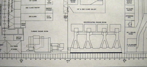
Titanic's Engine Rooms
Part I: Steam into Speed
TRMA Tech Feature of the Month
February 2006
by Art Braunschweiger, TRMA
with technical information provided by Scott Andrews
Titanic's boilers, consuming approximately 650 tons of coal a day, turned water into the high-pressure steam needed by the engines. How it was utilized in the engine room, and how it was returned to the boilers in the form of water for re-heating, is the subject this two-part article.
Each boiler normally produced steam at a pressure of 215 pounds per square inch
(PSI). Running overhead through each boiler room were two main steam pipes.
The steam from each boiler led into one or the other of these pipes, which
gradually increased in size as they approached the engine room.
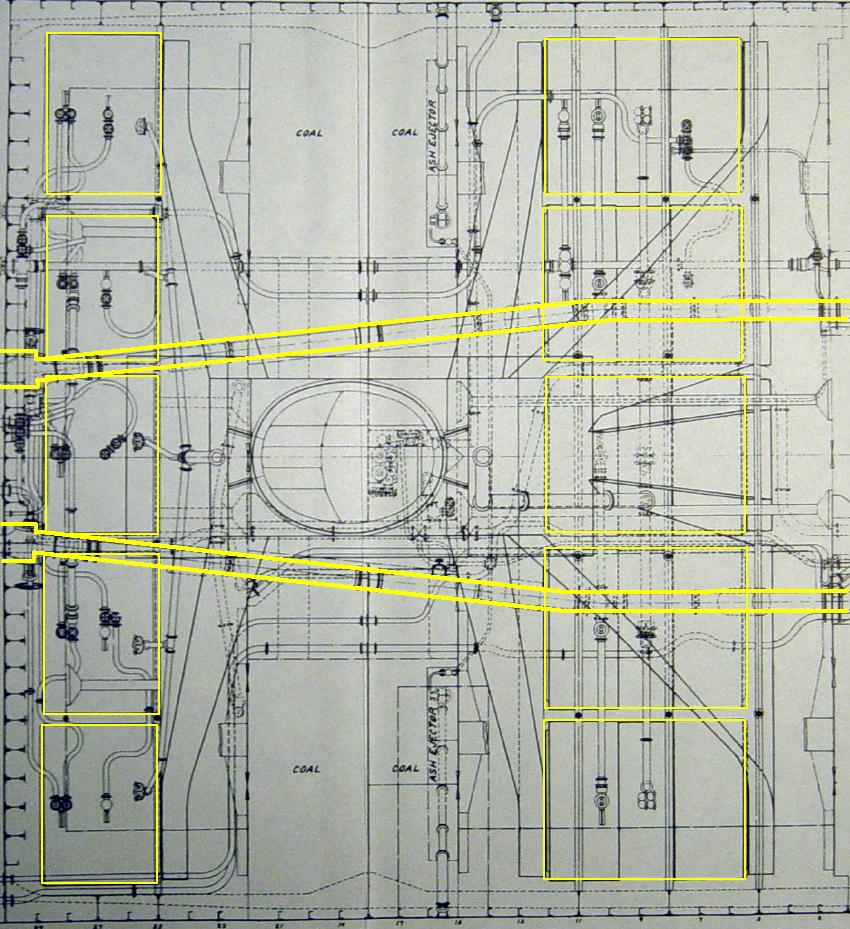
Overhead plan view of boiler rooms 1 and 2, showing route of steam pipes toward reciprocating engine room at left
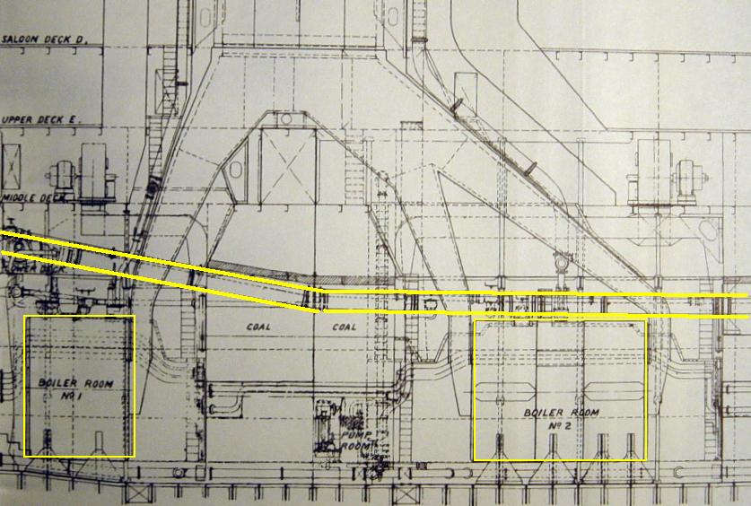
Elevation drawing of boiler rooms 1 and 2, showing steam pipes running above boilers toward reciprocating engine room at left
At the point where the steam pipes entered the engine room, they were 21 inches in diameter. Once the steam pipes passed through the last watertight bulkhead into the engine room, each steam pipe terminated at a quick-acting balanced emergency stop valve, which could be closed in a few seconds from the engine room floor in case of rupture of the line. Between the emergency stop valves, a cross-connection was provided between these two pipes so that the steam supply from either pipe could be used to power both engines together, or one by itself while the other engine was shut down. From the emergency stop valves, the steam was then directed through two large separators – one for each reciprocating engine – which trapped and drained away any condensed vapor or hard contaminants which may have formed in the steam supply piping. From the separators, the steam flowed to the “main stop”, or throttle valves.
Titanic had two reciprocating engines, one on each side, as shown in the plan view below:
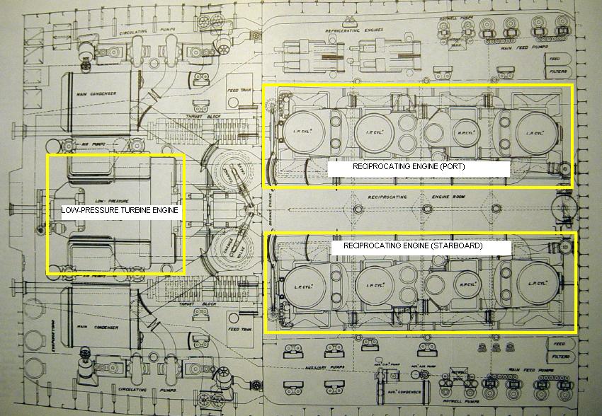
Overhead plan view of engine rooms. The reciprocating engine room is at
right, and the turbine engine room is at left. The watertight bulkhead
separating the two can be seen running vertically through the drawing
immediately to the left of the reciprocating engines.
The term "reciprocating" comes from the mechanical motion of the pistons inside the engine's cylinders, which move up and down in a reciprocating motion. The motion of each piston, by means of a large piston rod, helped turn the large crankshaft below. In fact, these massive engines were constructed on similar lines to an automobile's internal combustion engine, the key difference being that instead of the expansion of burning gasses being used to move the piston in each cylinder, the expansion of steam was used for the same purpose. Another significant difference is that, unlike the engine in a car, where the piston is only driven in one direction, steam reciprocating engines are “double-acting”. This means that steam is admitted first to one side of the piston and then the other, driving the piston both down and then back up. Additionally, there are no “cycles” as found in internal combustion engine; every stroke of the piston, up or down, is a “power stroke”, near the end of which the expanded steam is released from one side of the piston just shortly before the steam is admitted on the opposite side, driving the piston again in the opposite direction.
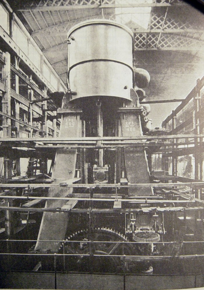
After end view of the starboard engine of Olympic in the Harland & Wolff engine works
The steam supply, coming straight off the boilers, was initially piped to the throttle valves located at the receiver of high-pressure cylinder on each engine, where it arrived at a pressure of 210 PSI. After this high-pressure steam expanded in this cylinder, thereby driving the piston up or down, and losing some pressure in the process - it was exhausted out of that cylinder at a pressure of 78 PSI, and directed into the next, or intermediate-pressure cylinder. Here the steam was used again, to drive the piston up or down in the cylinder. From here, having been expanded again, the steam was exhausted at a pressure of 24 PSI and was piped into two low-pressure cylinders for use again. Because the same supply of steam was expanded in three stages, Titanic's reciprocating engines were known as triple-expansion type. Each was designed to produce 15,000 horsepower at 75 revolutions per minute - far slower than an automobile, which runs at one or two thousand rpms, but vastly more powerful.
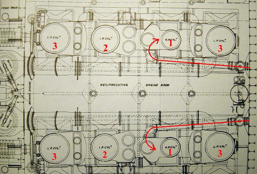
Overhead plan view showing high-pressure, intermediate-pressure, and low-pressure cylinders
As with an automobile engine, the engine was mechanically arranged so that each
cylinder "fired" at slightly different times, thereby transmitting energy to the
shaft in a coordinated and continuous manner.
When the steam left the low-pressure cylinders, it was exhausted at a pressure
of 9 PSIA (pounds per square inch, absolute). The difference between
“PSI” - also known as PSIG, or “pounds per square inch, gauge” - and “PSIA”
here is very important, as “PSI” is a measurement of pressure above that of the
atmosphere at sea level, which is approximately 14 PSIA; so, it can be seen here
that the low pressure cylinders were actually exhausting steam at a pressure
below atmospheric pressure. This was possible due to the terrific vacuum
created at the exhaust side of LP cylinders by the cooling of the steam being
exhausted from the engines into the condensers. (More will be said about the
condensers a bit further along.) Even though it would seem that every last bit
of available energy had been gotten from the steam at this stage, there was
still considerable latent energy that could be extracted from this steam, though
not by any reciprocating engine: this is where the low pressure turbine came in.
Overhead plan view showing pathway of exhausted steam from low-pressure cylinders on reciprocating engines to low-pressure turbine, and then to condensers
Unlike a reciprocating steam engine, a turbine can be designed to produce power from the continued expansion of steam all the way down into the high vacuum range that exists within the condensers. The turbine driving the center screw of the Titanic was designed to utilize the steam exhausted from the reciprocating engines at a pressure of 9 PSIA, expanding this steam all the way down to a terminal pressure of 1 PSIA, at which point, the steam – now virtually a warm fog - was exhausted into the main condensers.
A steam turbine is designed to operate something like a windmill. Using this
analogy and modifying it somewhat will help to understand how a turbine works --
imagine a windmill with a hundreds of very small blades, rather than 6 or 8
large blades. Then, assemble many rings of such blades - like connecting
multiple windmills front-to-back on the same shaft – and place it inside a large
cylinder, or housing, and you have the basic concept of a turbine engine.
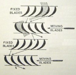
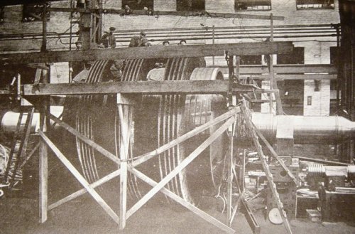
At left, photo of Britannic's turbine under assembly. The rings of blades can be clearly seen. At right, a drawing of turbine blades (from Heat Engines, by D. A. Low)
Although it used steam at a pressure of only 9 PSIA, the turbine engine was
designed to produce a considerable amount of power - 16,000 horsepower at 165
RPMs. Unlike the reciprocating engines, the turbine engine could not be run in
reverse and so a means for the steam to bypass the turbine engines had to
be incorporated into the system. When the reciprocating engines were running in
reverse, a pair of large changeover valves routed the steam from the
reciprocating engines directly to the condensers, bypassing the turbine
entirely.
Overhead plan view showing pathway of exhausted steam from low-pressure cylinders on reciprocating engines directly to condensers, bypassing the turbine engine.
Next month:
Part 2 - Back to the Boilers: Condensing the steam into feedwater
and returning it for re-use
Have a question on this subject? Post it on the TRMA Titanic Forum.
All engineering diagrams from The Shipbuilder, 1911.
Copyright © 2005 Titanic Research & Modeling Association
www.trmaarchive.com