For the modeler, two tables of information are also included: one listing all rigging with the actual sizes and scale equivalents, and a second table listing different model rigging materials and their scale sizes. Full information is also provided about model rigging materials and sources.
This Rigging Reference does not cover detailed modeling techniques or instructions on to how to rig your model. See the Rivet Counter Tutorial for further information.
Note on diagrams: All diagrams will open in their own window. When the diagrams first open, they are in reduced size to fit the window. To expand them to full size, move your cursor over the diagram and wait. At the bottom right corner of the diagram, an orange box with 4 blue arrows will appear. Clicking on this icon will expand the diagram to full size.
 For
those to whom rigging is a new subject, a great deal can be learned simply by
studying the diagram to learn the names of the different lines and their
functions A few basics, however:
Standing rigging refers to those lines that are permanently fixed to the ship, such as the stays that provide support for the masts. It can also refer to rigging that is temporarily fixed to the ship, such as for supporting cargo hoist lines. Standing rigging cannot be hauled upon and does not run through blocks or pulleys. Standing rigging was fastened to the deck by splicing it with a thimble to a large rigging screw (turnbuckle) so that the tension could be adjusted as required. Stays provided fore and aft support for the masts, and shrouds provided support to the sides. The wires supporting the funnels were also called shrouds.
Running rigging refers to lines that run through blocks or pulleys for purposes of applying a pulling force. Running rigging was used to raise and lower cargo, hoist signal flags, and for similar purposes. Some running rigging was left in place all the time (example – signal halyards), while some running rigging was set up only when needed (example – lines for hoisting cargo.)
By its nature, running rigging was rarely constant. How high a block was hoisted on a line or where a line was tied off on deck often changed every time the line was handled. Similarly, a cargo line may be in place in one photo and absent in the next. However, some lines were normally secured in the same place all the time.
Due to Titanic’s very brief service life, the appearance of her running rigging can be fixed to the point of her departure from Southampton, extending, based on a lesser number of photographs, to her final stop in Queenstown.
Titanic’s masts
were not ornamental, nor were they merely a holdover from the days of sail. The
masts functioned to carry the wireless aerial aloft and to support the derrick
and rigging for cargo handling, plus signal and flag halyards. The mast near
the bow was the Foremast, and the mast at the aft end of the ship was the
Mainmast.
.
S - Steel wire rope. The standard material for standing rigging was Galvanized Steel Wire Rope (GSWR). When left in its natural state, it was a dark silver-grey color. Running rigging used a finer-stranded variant with a hemp rope core, called Flexible Steel Wire Rope (FSWR). It was more flexible and therefore capable of bending more sharply, making it suitable for running through blocks (pulleys) where great strength was also required.
H - Hemp rope. Made from the fibers of the Hemp plant, it is very durable and extremely flexible. This made it suitable for light hoisting through small blocks. Hemp rope has a grey-brown color. If hemp was used as standing rigging or in any semi-permanent situation, it was normally tarred since hemp absorbs water.
M - Manila rope. (sometimes incorrectly called “manila hemp”). Made from fibers of the Abaca plant, its strength and flexibility are comparable with hemp, and it also has good elasticity. However, unlike hemp, manila rope is unaffected by salt water. These factors combine to make manila more suitable than hemp for non-steel lines that must carry a load, where degradation and loss of strength cannot be risked. This also makes manila the most suitable material for hawsers (mooring lines). Manila rope has a dark golden-brown color.
B
- Silicon bronze wire. This alloy, used for the
Marconi aerial wires, possesses a very high tensile strength along with high
conductivity - altogether, very desirable qualities for a ship’s aerial antenna
array. In Marconi
specifications the
wires are shown as 7/19, but this does not refer to the size – it refers to a
cable of seven wires of 19 strands each.
The TRMA Rigging Diagram shows how Titanic was rigged at the time of departure from Southampton on April 10, 1912. Most important for the illustrator or modeler, it shows exactly how the rigging appeared – how much slack was in each line, if any, and exactly where all running rigging was secured. (The diagram does not list line sizes. For this information, see the Rigging Table.)
The Rigging Diagram also does not include the derrick rigging for use in port. This is covered in a separate section. It also does not include any lines used to secure the ship to the dock – those are mooring lines, and not considered part of the ship’s rigging.
All the rigging shown on the diagram is based on original Harland & Wolff rigging plans. However, the H&W rigging plans for the Olympic-class ships do not show all the running rigging, or in some cases indicate the presence of rigging without specific reference to how it was set up. Photographs and photographic analysis were used to determine and verify the location of all running rigging shown on this diagram, and different photographs taken from different angles were studied to confirm or rule out the location of all rigging. Where the location of a line is uncertain, it has been noted as such.
In the course of this research, new details emerged about Titanic’s rigging. For some rigging details, it was discovered that photographic evidence does not support the way some rigging appears in illustrations or model directions. All rigging that is definitively indicated on the Rigging Diagram has been verified and questions or requests for supporting evidence are welcome - please contact the author or post on the TRMA Forum.
Terms as used on the rigging plan are taken from rigging plans of the period, not limited to the Olympic-class ships, and are the terms that were in common use at the time. (For modelers not familiar with block-and-tackle terminology and the various configurations (purchases) referenced in the diagram, they are diagrammed separately on the Appendix Page. This page also has photographs of some specific rigging details.)
To go to the full-size rigging version, click on the diagram (550kb). The full size as it's designed to be printed is approximately 15" x 63". If you desire a hard copy for reference, it’s recommended that you save it to a CD and then take it to a commercial copy center to have it printed. Make sure that you specify this size, otherwise you may end up with a copy that's too small. Note that color is usually very expensive to print, whereas black-and-white is not. A cost-effective option is to have it printed in black-and white, referencing the color version on your computer as necessary.
Anyone who has seen a photograph of Olympic or Titanic with lines rigged for cargo handling will attest that it presents a very confusing picture. In the photograph below of Olympic at New York, apparently taken at the noon break, there appear to be lines running everywhere - yet every line has a purpose. It may help to know that multiple cargo lines were in operation at the same time; and in the case of the foremast derrick, multiple lines were required to raise it, lower it and move it side-to-side.
For
working the #1 hatch on the forecastle deck (seen just forward of the V-shaped
breakwater, above) a wire rope called a cargo span was rigged over it. This
line, shown in green on the main Rigging Diagram, was run from the mast near
the top of the ratlines to the prow at the forward end of the bows. In
the center of the span, over the hatch, steel blocks with cargo lines (“cargo
runners”) were rigged to service the hatches. A similar cargo span was
also rigged over the fore well deck to service the #2 and #3 hatches.
This cargo span, with two cargo runners, appears in the photos of Titanic
departing Southampton. There were actually attachment points for two cargo
spans on the roof of the officer’s deckhouse, but only one was used at Southampton.
And the foremast derrick,
while it could serve as a primary means of loading and discharging cargo directly
between the holds and the dock, could also be fitted with cargo runners midway
along its length. Finally,
two cargo spans could be rigged over the aft well deck to service the # 5 and
#6 hatches, although no photographs show either rigged in that location during
Titanic’s brief life. (Remember that there were four electric
cranes positioned to serve the aft well deck, whereas there were only two at
the forward well deck.) In all cases, the ship’s winches provided power
for all raising and lowering of the ship’s cargo runners. Several could
be in use at any given time, since each winch had multiple drums.
Click on the diagram above right to view the foremast derrick as it would have been rigged for cargo handling in port. It's also interesting to note that Titanic and Olympic's foremasts were each fitted with a step for a second derrick over the forecastle deck. (Photographs of Olympic during her fitting-out period show a second derrick in use.)
 Not
all cargo or supplies
was loaded directly from the dock into the holds. At
Southampton, the massive cranes on the dock frequently operated in concert with
the ship’s cargo handling lines. The dockside crane could either deposit
the load on deck near the hatch where it would be picked up and actually lowered
into the hold by the ship’s cargo runners or electric cranes, or the shore crane
could transfer the weight to the ship’s cargo runners with the load in mid-air.
Discharging cargo would have been done in reverse.
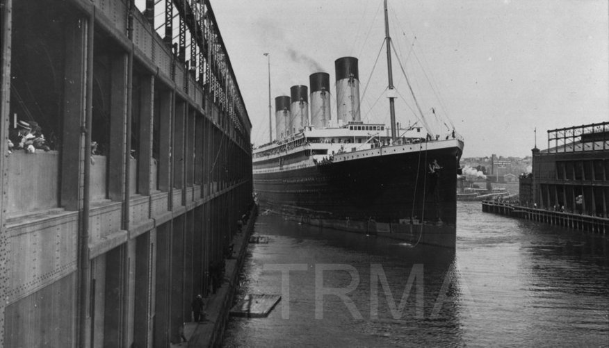
At New York, a different system had to be used. As the photo to the right shows, the sides of the pier buildings ran right along the water’s edge. Thus, there was no room for dockside cranes as at Southampton. Instead, the pier buildings had cargo rigging integral to the building’s structure: the vertical steel beams of the walls were, in effect, extended up through the roof, and near the top of each was a large pulley. Wire rope lines, often termed house falls, ran up and over these pulleys and then back down through the roof to winches inside the building. (For anyone who has seen the New York passenger ship terminal buildings, this open structure of girders along the roof line suddenly takes on new meaning!) Cargo loads would have to be transferred between pier and ship using the house falls and the ship's cargo runners working together, transferring the load gradually from one to the other as the load was raised up and over the side of the ship.
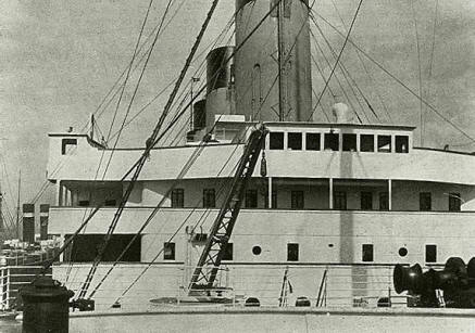
As with the cargo lines, in photographs of Titanic departing Southampton there are a few lines that appear in positions different from where they would be secured at sea. For example, in the only shot of Titanic's forecastle, taken by Father Browne at Southampton, a line is tied off to the starboard railing, most likely for convenience or to move it away from other lines or gear being handled. Similarly, in this same photo, several hawsers can be seen coiled against the breakwater (as in the Olympic bow shot, above). None of these lines would have been left in place: in the process of securing the deck for sea, the hawsers would have been stowed below and any lines temporarily belayed to the railings would have been belayed more securely elsewhere. It was not unknown for heavy seas to sweep the decks of even the largest Atlantic liners, and the prospect of a hundred fathoms of 9-inch line being carried overboard to foul the screws would be a nightmare of unimaginable proportions. Consequently, all lines that did remain in place had to be secured against the highest winds, and such that a breaking seas could pass around them or under them without effect. Lines coiled on deck or loosely tied to railings do not meet that requirement.
Flaglines for dressing ship
Flaglines were flown on ceremonial occasions. Titanic’s were flown on one occasion only, following her arrival at Southampton
The Fore-to-Main line was stablized by two stays along its length to prevent the flagline whipping up and over the Marconi array. One stay was located forward of the second funnel, and the other was located aft of the 3rd funnel. Both ran down to the Boat Deck.

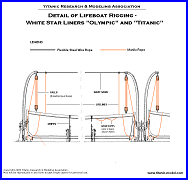 Lifeboat
and Davit Rigging -
This is detailed in a separate diagram. Click on the diagram to access
it.
All
of the actual line and wire sizes as they were used on the ship are listed in
the table at right. Click on the table to access it. (One
important note regarding wire sizes: British rigging plans of the period
specified wire and rope sizes in circumference, not diameter. Both are
listed here.)
This table also lists the scale equivalents in 1:350 and 1:144 scale. The scale equivalents specify the actual diameter of the lines that should be used on a model to accurately replicate the lines that were on the ship. In the Model Rigging Materials section below, there is a second table that lists the various materials available, their actual diameters and their equivalent sizes in the two scales mentioned. Using the two tables together, you can knowledgeably make a decision as to what rigging materials will be best for you, and if desired, rig your model with dead-on scale accuracy.
Scale size in inches has
been rounded up to nearest thousandth of an inch, as most micrometer calipers do
not read beyond this degree. All calculations done to four significant figures
prior to rounding.
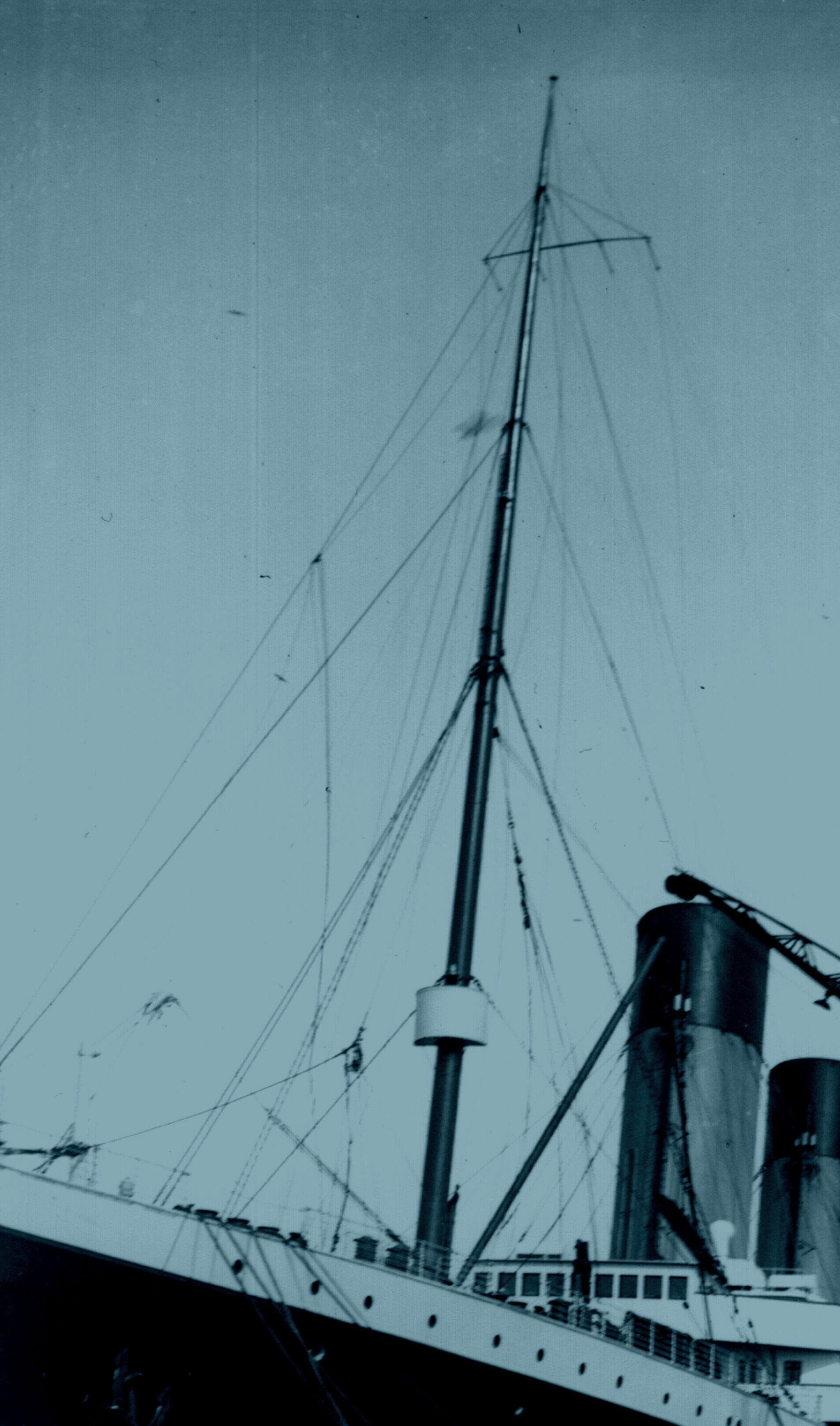
First, a note on scale sizes: most ship models are rigged with line that is far too heavy. Even the heaviest rigging on the ship did not stand out from a distance, and the lighter rigging was nearly invisible. Most of the rigging that can be seen on Olympic, below, is visible only because of the dark cloud background. In bright sun, the lighter rigging and the Marconi array tended to disappear altogether. On a scale model, the rigging should be visible but very unobtrusive, just as seen here. (This photo is of Olympic and is for illustration only. Not all rigging was identical between Olympic and her sisters.)
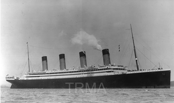
Unlike this ship, a model is seen up close, and usually viewed from above – not from below, against a bright sky. For this reason, any rigging on a model will be more visible than on a real ship, so it’s important not to “over-model”. But by making intelligent choices, a modeler can easily and accurately model Titanic’s rigging and spend no more than a few dollars in the process. (If you want a well-rigged but more basic model, consider eliminating the stay travelers, the gantlines (painters’ lines) on the funnels, and the flag halyards that ran to the mast tops. Eliminating the stay travelers is especially recommended if you’re using only thread to rig your model.)
Following
are various materials available. (Sources for each are listed after this
section.) The table at right lists the exact diameter sizes and their
scale equivalents for the above materials. Click on the table to access
it. Also note that some of these materials also have modeling applications
other than rigging – piping, handrails and such. For this reason a number
are listed for sizes well beyond what’s appropriate for rigging.
Nylon monofilament (fishing line) - Previously recommended by some sources, it’s generally unsuitable based on its size. The diameter of the smallest line available is too large, even for 1:144 modelers. (The only exception in 1:144 scale is the funnel stays and mast stays). In addition nylon line is glossy, and must be painted. (It does possess the advantage of being easily tensioned by applying heat from a hair dryer.). It’s mentioned here only to explain why it should not be used in preference to the other materials listed.
Polyester fly-tying thread - an outstanding rigging material. It’s fairly scale-accurate for most of the rigging, it’s very inexpensive, easy to use, and available in the correct colors.
Note: the thread that is supplied with the newer (re-released) Minicraft kit is approximately the right scale size for the mast and funnel stays if you’re building a basic model and want to use one rigging size for simplicity. It’s also very high quality. However, the black color tends to make it stand out more than it should, and the thread has kinks in it every two inches from the card it’s wrapped around which are difficult to remove. Fly-tying thread is available for under two dollars per spool, and considering the importance of the rigging as a finishing touch, is a recommended investment.
(One modeling tip is worth including here: To eliminate the waviness inherent in flytying thread after unspooling, cut a section longer than required and stretch it taught before rigging it, and apply heat from a closely-held hairdryer along its length. By doing this even the Marconi wires, which require a significant catenary (droop) along their length can be modeled with a perfect appearance. Also consider a little beeswax run on the thread, and then running the thread through your fingers, for protection and longer life - but do this before securing the thread to your model, and stay away from glue points and where paint will be applied.)
Nylon
sewing thread –
This is an acceptable substitute for the modeler who may want the convenience of purchasing from a local store rather than mail-ordering flytying thread. However, there are significant differences in diameter between different types and manufacturers of thread, whereas flytying thread can be depended on for more consistent and accurate sizes for the same cost. If your choice is to use this material, purchase the finest thread available and make sure you choose the appropriate color(s).
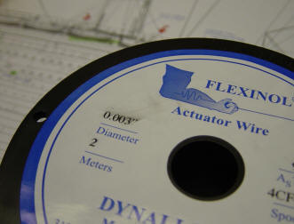
Nitinol – This is Nickel-Titanium wire, originally developed by the US Naval Ordinance laboratory. Its value to modelers is in its exact scale accuracy and resistance to kinking. While the color is a bit too dark (tending toward gunmetal), its advantages overshadow this one flaw. It also gives the appearance of steel wire much better than thread. Its use will add about $20.00 to the cost over fly-tying thread for basic rigging (much more if you’re using it for all the lines), but for modelers willing to spend the extra amount, a superior model will result.
Nitinol is available inexpensively in only a few sizes. Flexinol, a variant of Nitinol, is available in the other scale sizes required, but is considerably more expensive ($1.37 per foot in the US, compared to 15 cents per foot for Nitinol.). As a compromise to avoid purchasing the more expensive material, some modelers may elect to use just the larger size to model the stays. The term Nitinol is used in this Reference to refer to both Nitinol and Flexinol.
Hair – as odd as it sounds, one modeler in Australia reports using it with great success. It actually has a lot going for it – it’s very strong, it won’t kink, it can readily be secured with cement, and it’s the right scale size for general all-purpose rigging.
 Recommended
sources and brand names
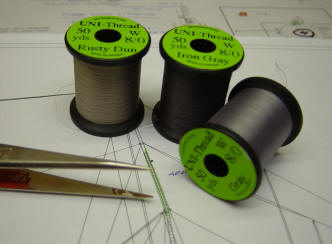
If possible, look for the brand name Uni-Thread. Uni-Thread is very high-quality and available in the range of colors required. It is normally available in only two sizes suitable for a modeler working in 1:350 scale: 6/0 and 8/0. (The smaller the number, the larger the size). In general, the larger 6/0 size can be used for the stays and shrouds, and the smaller 8/0 size can be used for all other rigging.
Colors suggested within the Uni-Thread line:
Standing rigging: Grey (this color in the Uni-Thread line is a light grey, which is correct.)
Running rigging (steel wire rope) :
- Grey if rigging with all thread
- Iron grey if using Nitinol for standing rigging (to avoid an undesirable color contrast. However, Iron Grey color is not available from all Uni-Thread dealers)
Running rigging: Dun. See note below.
Marconi wires:
- Dun for tarred hemp lines aft (see note below)
- Rusty Dun, if available, for silicon bronze wires forward, otherwise use Grey.
Note: For historical accuracy, Brown thread (dark brown) should theoretically be used for hemp lines. However, the color is too dark for good scale appearance. The lighter Dun color also gives the thread a finer appearance and makes it less visible – both very desirable qualities for the lighter rigging.
Sources:
As fly-tying thread is widely available on-line and through local fishing and sporting goods stores, and as Internet catalog pages change frequently, no sources have been listed here. An Internet search should yield numerous suppliers if a local store can’t supply the desired spools.
 Note:
Nitinol vs Flexinol: in some sizes, both are available – where a choice exists,
always use Nitinol. The handling characteristics are identical. You may also
have to choice between different “actuating temperatures”. The choice does not
matter for modeling
http://www.dynalloy.com/PriceGuide.html
http://www.rapideducation.co.uk
Sizes are listed in microns. For comparison with the scale sizes listed in the
table above,
50
µm =
.002” and 150
µm =
.006”.
Full range of sizes, but very expensive. Sizes are also listed in microns.
(Micron size x .00004 = size in inches.)
If any reasonably-priced sources are known other than the ones listed, please forward them to the author through the TRMA Forum and they will be included here.

Questions or comments on any information provided here or on the Rigging Diagrams? Post them on the TRMA Forum.